FEATURES
FOREWORD
1
2
•AVCS system
Since rudder trim changes caused by wind and other meteorologi-
cal changes and front, rear, forward, reverse, and other helicopter
attitude changes are automatically cancelled, tail (rudder) opera-
tion is easy, making it perfect for 3D flight.
•SMM gyro sensor
Use of newly developed extremely low drift SMM (Silicon Micro
Machine) gyro sensor virtually eliminates rudder trim changes
during flight.
•Digital servo compatible (DS mode)
DS mode makes it compatible with Futaba digital servos. Maxi-
mizes the high-speed response performance of the digital servo.
•Remote gain function and mode switching func-
tion
Remote gain function allows sensitivity switching from the trans-
mitter and mode switching function allows AVCS/normal gyro
mode switching.
•Integrated, compact, and lightweight
Compact size (27x27x20mm) and light weight (27g) realized by
high density mounting technology.
•Conductive resin case
Conductive resin case improves EMC (electrostatic and electro-
magnetic interference) resistance.
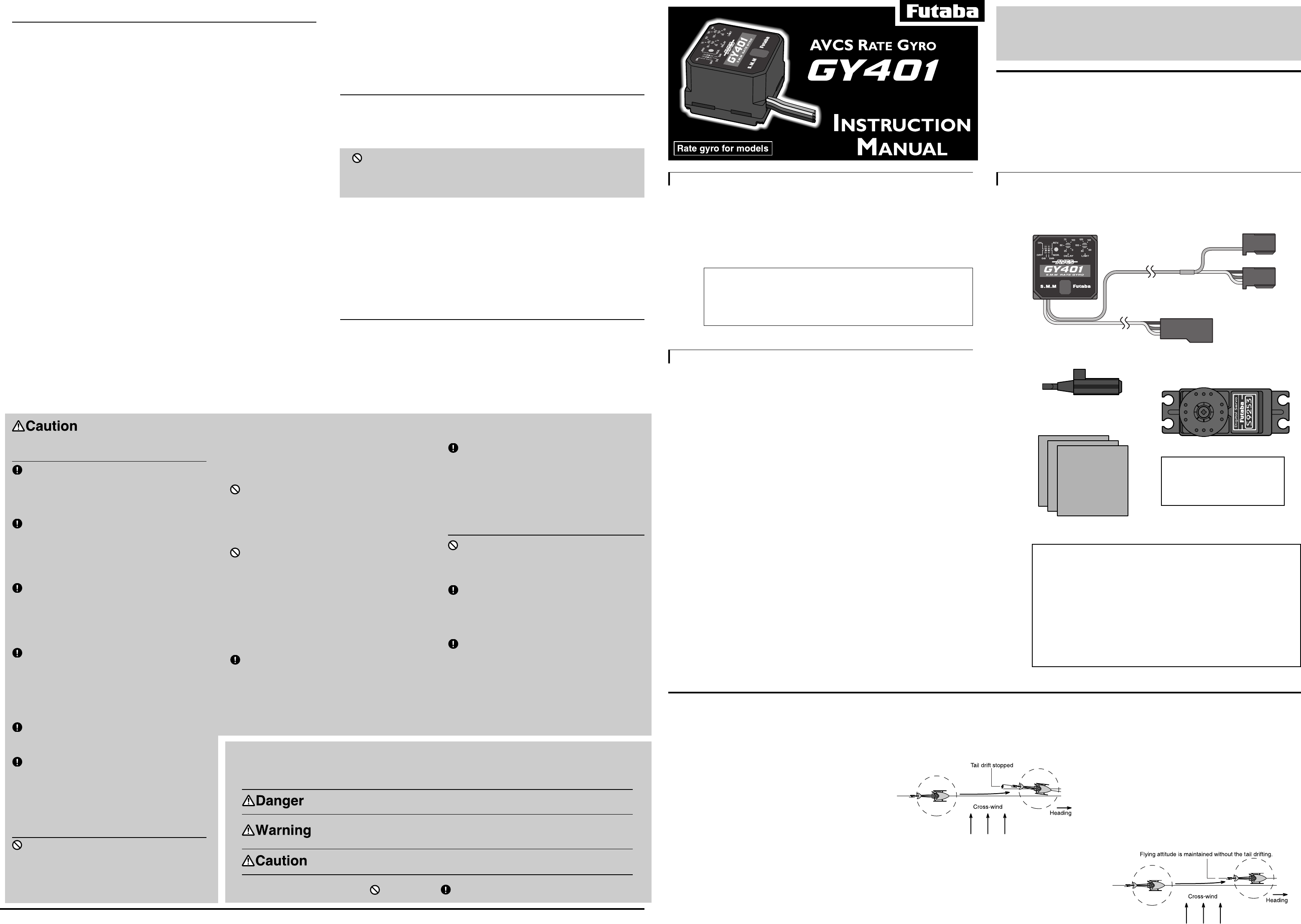
SET CONTENTS
3
•GY401
•Double-sided tape
(3 sheets)
The GY401 is a high performance, compact, light weight AVCS
(Angular Vector Control System) gyro developed for model
helicopters. Because the sensor and control circuit are integrated,
it is simple to install.
S9253 Ratings
(Digital servo for gyro)
•Speed: 0.08sec/60˚(at 4.8V)
•Torque: 2.0kg-cm(at 4.8V)
•Dimensions: 40x20x36.6mm
•Weight: 49g
•S9253
(Only a set w/servo)
Applicable servos
Gyro performance largely depends on the servo used. The
higher the speed and response of the servo, the better the gyro
sensitivity and performance. From this standpoint, a digital
servo is perfect for use with this gyro. The S9253 high-speed
digital servo developed especially for gyro use is recommended.
• No part of this manual may be reproduced in any form without prior permis-
sion.
• The contents of this manual are subject to change without prior notice.
• This manual has been carefully written. Please write to Futaba if you feel that
any corrections or clarifications should be made.
Thank you for buying a GY401 AVCS gyro.
Before using your new gyro, please read this manual thoroughly and
use the gyro properly and safely. After reading this manual, store it
in a safe place.
1M23N08102
The GY401 comes with the following accessories:
•Mini screwdriver
(for adjustments)
GY401 Ratings
(Integrated sensor type AVCS rate gyro)
• Control system:
Digital advanced PI (Proportional Integration) control
• Gyro sensor:
SMM (Silicon Micro Machine) system vibration gyro
• Operating voltage: +4 to +6VDC
• Operating temperature range: -10˚C to +45˚C
• Dimensions: 27 x 27 x 20mm
• Weight: 27g (including connector)
• Functions:
Gyro operation direction switch, DS mode switch, Control delay
trimmer, Limit trimmer, Remote gain control, AVCS/normal mode
switching
AVCS Gyro
Conventional gyros send control signals to the
rudder servo only when the tail of the helicopter
moves. When the tail stops moving, the control
signal from the gyro becomes zero. Conversely,
the AVCS gyro continues to send control sig-
nals to the servo even when the tail of the
helicopter stops moving.
The following sequentially describes the con-
ventional gyro and the AVCS gyro.
Operation of Conventional Gyro
Basic operation is described by considering the
case when the helicopter is hovering under
cross-wind conditions. With a conventional
gyro, when the helicopter encounters a cross-
wind, the force of the cross-wind causes the tail
of the helicopter to drift. When the tail drifts,
the gyro generates a control signal that stops the
drift. When the tail stops drifting, the control
signal from the gyro becomes zero. If the cross-
Operation of AVCS Gyro
Conversely, with an AVCS gyro, when the
helicopter encounters a cross-wind and the tail
drifts, a control signal from the gyro stops the
drift. At the same time, the gyro computes the
drift angle and constantly outputs a control
wind continues to cause the tail to drift in this
state, the "stop" operation is repeated until the
tail faces downwind. This is called the
"weathervane" effect.
signal that resists the cross-wind. Therefore,
drifting of the tail can be stopped even if the
cross-wind continues to effect the helicopter. In
other words, the gyro itself automatically cor-
rects (auto trim) changes in helicopter tail trim
by cross-wind.
Considering operation of an AVCS gyro, when
the tail of the helicopter rotates, the servo also
rotates in accordance with the angle of rotation
of the tail. When the tail stops rotating, the servo
judges that it has stopped in that position. This is
the auto trim function.
Fuselage Maintenance
Precautions
Do not turn the sensitivity trimmer with
too much force.
The trimmer may break. Always use the miniature
screwdriver supplied to make adjustments.
Make positive maintenance of the fuselage
tail section a habit.
The rigidity of the tail section has a large effect on gyro
performance. Therefore, loose supporter and tail pipe
aging also have a large effect on the characteristics.
Service the fuselage with a little vibration
as possible.
Fuselage vibration has a very adverse effect on gyro
performance.
Mounting Precautions
Always use the accessory sensor tape to
install the gyro to the fuselage.
This is necessary to securely fasten the gyro to the
fuselage so that operation of the gyro does not transmit
unwanted fuselage vibrations directly to the sensor.
When mounting the gyro, provide a little
surplus so that the gyro connection cables
are not too taut.
If the gyro cables are too taut, the gyro will not display its
full performance. If the gyro peels, control will be lost
and result in a dangerous situation.
When using the gyro with a helicopter,
install the GY401 at least 10cm from the
drive motor.
The drive motor generates strong electromagnetic noise.
This noise may interfere with the gyro sensor and cause
erroneous operation.
Mount the GY401 so that metals or other
conductive objects do not touch the gyro
case.
The GY401 uses a conductive resin case to reduce
electromagnetic interference. Because the surface of the
case is conductive, metal objects may cause a short
circuit.
Insert the connectors fully.
If a connector works loose due to vibration during flight,
control may be lost and result in a dangerous situation.
Always check the direction of operation of
the servos.
If you attempt to fly the model when a servo operates in
the wrong direction, the fuselage will spin in a fixed
direction and enter an extremely dangerous state.
Operation Precautions
Never move the fuselage for about 3 sec-
onds after turning on the gyro power
(shared with receiver).
Since the data inside the gyro is automatically initialized
as soon as the power is turned on, if the fuselage is
moved, the neutral position will change. If this occurs,
FUTABA CORPORATION
Makuhari Techno Garden Bldg., B6F 1-3 Nakase, Mihama-ku, Chiba 261-8555, Japan
Phone: (043) 296-5118 Facsimile: (043) 296-5124
©FUTABA CORPORATION 2000, 7
Special Markings
Pay special attention to the safety at the parts of this manual that are indicated by the following marks.
Mark Meaning
Procedures which may lead to a dangerous condition and cause death or serious injury to the
user if not carried out properly.
Procedures which may lead to a dangerous condition or cause death or serious injury to the
user if not carried out properly, or procedures where the probability of superficial injury or
physical damage is high.
Procedures where the possibility of serious injury to the user is small, but there is a danger of
injury, or physical damage, if not carried out properly.
Symbol: ; Prohibited ; Mandatory
Check the operating time of the receiver,
gyro, and servo batteries at the adjustment
stage and decide the number of remaining
flights while allowing a margin.
turn the power off and on again. When turning on the
power, set the transmitter switch to the AVCS position
and turn on the transmitter power switch, then turn on the
gyro power.
Do not operate the rudder trimmer while
flying in the AVCS mode.
When the power is turned on, the GY401 assumes that
the rudder stick is in the neutral position. If the rudder
trimmer is moved during flight, the neutral position will
change.
Avoid sudden temperature changes.
Sudden temperature changes will cause the neutral
position to change. For instance, do not fly the model
immediately after removing it from inside a heated
vehicle in the winter and an air conditioned vehicle in the
summer. Let the model stand for about 10 minutes to
allow the temperature inside the gyro to stabilize before
turning on the power. Also, consider sudden temperature
changes when the gyro is exposed to direct sunlight or is
installed near the engine. Take measures so that the gyro
is not exposed to direct sunlight.
When using the gyro in the AVCS mode,
set revolution mixing to 0% or OFF.
In the AVCS mode, all rudder corrections are made by
the GY401. Therefore, if rudder mixing is ON, the model
will operate the same as if the neutral position changed.
Using the AVCS mode correctly
An AVCS gyro is an angular velocity command type gyro. The gyro con-
stantly compares the transmitter rudder operation signals and gyro internal
reference signal (transmitter rudder neutral signal) and controls the helicop-
ter tail rotation speed accordingly. Therefore, for the AVCS function to
operate normally, the rudder neutral signal must be memorized in the gyro
before flight.
•Rudder neutral signal memorization methods
[Method 1] When the gyro power is turned on, the transmitter rudder signal
automatically received at that time is assumed to be the neutral signal and
is memorized. The gyro is normally used in this state.
[Method 2] Rapidly switch the transmitter sensitivity switch between the
AVCS and normal modes at least 3 times at a 1 second or shorter internal,
then set the switch to the AVCS mode position. The monitor LED flashes
instantaneously and the rudder signal is memorized. If the trimmer was
moved during flight, the memorized neutral position can be updated to the
current neutral position by repeating this operation. When performing this
operation, land the model and hold the rudder stick in the neutral position.
•Rudder neutral check method
In the AVCS mode, the servo does not return to the neutral position even
when the rudder stick is returned to the neutral position. When you want to
check the servo neutral position during linkage neutral check, etc., select
the normal mode, or remain in the AVCS mode, and move the rudder stick
left and right at least 3 times at an interval of 1 second or less, then imme-
diately return the stick to the neutral position. This operation returns the
rudder servo to the neutral position.
•AVCS mode usage precautions
In the AVCS mode, always set revolution mixing to OFF. If revolution
mixing (pitch->rudder mixing) is ON, the pitch operation signal changes
the rudder neutral position. The gyro judges that an angular velocity com-
mand was received and rotates the tail, therefore, the neutral position
changes.
The model flies in the same rudder trim position (including sub trim) as
when the power was turned on (neutral position memorized in the gyro).
When flying in the AVCS mode, set the rudder trim to the same position
under all flight conditions, including hovering and idle up. In the AVCS
mode, the gyro automatically trims the rudder so that trimming during
flight and other precision rudder trim adjustments are unnecessary.
Other precautions
•DS switch setting precaution
When the DS switch is set to the ON position, the rudder servo is driven by
approximately 270Hz high-speed pulses. This mode is for use with Futaba
digital servos only.
When using servos that are not compatible with high-speed
pulse drive, other than digital servos, never set the DS switch
to ON.
The servo may be destroyed.
•Operation of trimmers, etc.
Miniature trimmers and switches are used with the GY401 to reduce its
size. When operating the trimmers and switches, always use the miniature
screwdriver supplied and do not apply excessive force.
•Servo small step operation
When the model is static, the servos may move a small step. However, this
is because the gyro sensitivity is set to a high value and is normal.
One point advice
•Relationship between servo horn length and gyro sen-
sitivity
Gyro sensitivity also changes with the length of the servo horn.
When the sensitivity is too low, length the servo horn. Conversely, when
hunting does not stop, shorten the servo horn.
 (2 pages)
 Manymanuals.com
 Manymanuals.de
 Manymanuals.fr
 Manymanuals.it
 Manymanuals.pl
 Manymanuals.cz
 Manymanuals.es
 Manymanuals-pt.com
Comments to this Manuals