Futaba 8SGAP User Manual
Browse online or download User Manual for Accessories communication Futaba 8SGAP. Futaba 8SGAP User Manual
- Page / 38
- Table of contents
- BOOKMARKS
- INSTRUCTION MANUAL 1
- Switch or Description Ref 3
- •FEATURES 4
- RECEIVER FP-R118GP 5
- SERVO FP-S130 5
- SERVO FP-S130G 5
- Servo FP-S130 6
- Battery Charger FBC-8B(2) 6
- •GLOSSARY OF TERMS 7
- •BASIC TRANSMITTER CONTROLS 8
- OPERATING INSTRUCTIONS 14
- ALARM SETTING 15
- TIME AND ALARM SETTING 15
- •RECEIVER AND SERVOS 16
- Set the DIFF 19
- ATV SETTING 20
- CHARACTER NAMEPLATE RC 21
- SET COMPATIBILITY 21
- PCM GREEN CHARACTER 21
- NAMEPLATE AND RED 21
- (CONVENTIONAL) 22
- •SERVO REVERSING SWITCHES 22
- •RUDDER AUTO DUAL RATE 24
- (VARIABLE 24
- TRACE RATIO) 24
- (ADJUSTABLE 26
- THROTTLE 26
- •SERVO TEST FUNCTIONS 28
- Pitch 0 (minimum) in slow 29
- Idle up lever 30
- Pitch 8-9 30
- •THROTTLE POSITION TRIMMER 31
- •AIRCRAFT WITH FLAPS 31
- Flaps 45 ~60 32
- •FLAP TRIM FUNCTION 33
- •MUTUAL (BI-DIRECTIONAL) 36
Summary of Contents
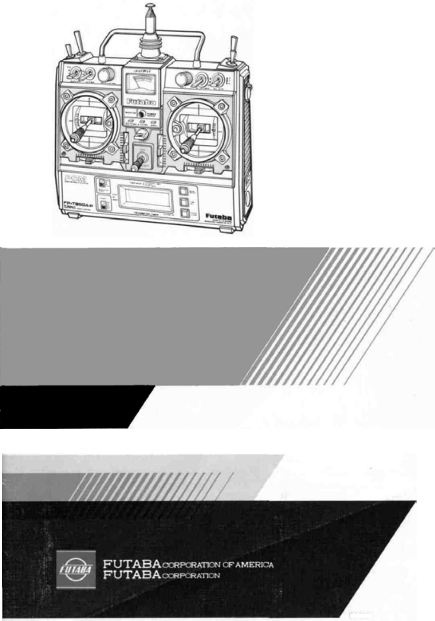
FutabaDIGITAL PROPORTIONALRADIO CONTROLPCMPULSE CODE MODULATION SYSTEMINSTRUCTION MANUALFP-8SGAPPCM 8 CHANNELS,FOR F3A AIRCRAFTD60354
MODE ISlantable stick adjusting screwsThe angle of the stick levers can be changed.Fig. 3Turn this screw with a Phillipsscrew-driver.The open gimbal s
Mini stand• Use this stand as shownin Figure when layingthe transmitter down.This makes operationeasier and protects theRF module andtransmitter bac
•BATTERIES AND CHARGING INSTRUCTIONS•The Direct Servo Controller system connectsthe signals from the transmitter directly toterminal C of the receiv
•TACHOMETER/TIMER OPERATIONLIQUID CRYSTAL DISPLAYDo not press the keys too quickly.Press them at a speed of about onceper second. |Do not expose the
Make all speed measurements outdoors undernatural lighting. Accurate speed measurementscannot be made indoors under artificial lightingbecause of t
Note do not expose the liquid crystal display todirect sunlight for a long time.Selects the tachometer/timer mode.This switch sets thealarm time.Memo
•RECEIVER AND SERVOSReceiver, Servo Switch, andBattery Connections8SGAP 4 ServosAileron servoElevator servoThrottleservoRudder servoLanding gear servo
•FP-S130 AND FP-S130G EXPLODED VIEWSFig. 22Fig. 23No.1.2.3.4.5.6.7.8.9.10.11.12.13.14.15.16.17.18.19.20.21.22.23.24.25.PartNameUpper caseMiddle caseBo
•SPLINED HORNSFig. 24The following splined horns are optional.HORN A HORN B HORN C HORN D HORN E HORN FFig. 25This horn permits shifting of the
•BASIC LINKAGES AND INSTALLATIONThe FP-8SGAP has a servo reversing switch and ATV (Adjustable Travel Volume) foreach channel. Mount the servos witho
Thank you for purchasing a Futabadigital proportional radio control set.Please read this manual carefully before using your set.
•USING ATV (ADJUSTABLE TRAVEL VOLUME)GENERAL - ATV (Adjustable Travel Volume)allows independent adjustment of servo maximumthrow in each direction (
CHANNEL SELECT SWITCH• This switch 48 selects the channel when settingFS and HOLD functions. It also acts as the chan-nel select switch for SERVO TE
•2ND ATV (CONVENTIONAL)2ND ATV is available on the aileron and elevatorchannels. This is the conventional type ATV and isset using trimmers [34], [3
•USING DUAL RATE(AILERON, ELEVATOR, AND RUDDER)Dual rate functions allow the flyer to alter themaximum servo travel (and therefore control sensi-tiv
•RUDDER AUTO DUAL RATE•This function automatically switches rudder D/R to ON as the throttle lever is moved from LOW to HIGHposition. This allows a s
•SUGGESTIONS ON ATV, D/R, AND VTRPOINTS TO REMEMBER (ATV, D/R, VTR)•Servo maximum deflection is always determinedby ATV. If no ATV is set, maximum t
•USING ATL (ADJUSTABLE THROTTLE LIMIT)HIGHFig. 44The Throttle Trim Lever 19 affects the servo po-sition only when the throttle control stick is in th
•FS (FAIL SAFE) AND HOLD FUNCTIONSHOW TO USE FS (FAIL SAFE) (THROTTLE CHANNEL AS AN EXAMPLE.)Set Function Select Switch 49 to FS SELECT.Set transmit
•SERVO TEST FUNCTIONS• The operation of the servos can be checked bysetting the transmitter and receiver powerswitches to ON.•When switch 49 is
•AIRCRAFT WITH VARIABLE PITCH PROPADVANTAGES OF VARIABLE PITCH PROPELLERThe variable pitch propeller offers such advantages as:1. The desired speed
TABLE OF CONTENTSINDEX FOR TRIMMER PANEL FUNCTIONSGENERAL INFORMATIONFeatures ...Contents and Ratings ...Glo
NOTE:When lowering lever 8 , be careful that the pitchdoes not go negative. This is adjusted during flight.For example, flight is affected by the t
•THROTTLE POSITION TRIMMERThrottle stick• (B) Throttle -> pitch control mixingThe pitch control servo mixing point can be setto an arbitrary point
•ELEVATOR/FLAP MIXINGELEVATOR -> FLAP MIXING• Switch 10 : ACT• Switch 18 : TRIM• Elevator -> Flap (2 -> 6) mixing is unidirectionalwith el
•AIRCRAFT WITH FLAPS AND SPOILERS(AIRBRAKE)Connect the Flap servo to CH6 and the Spoilerservo to CH7 on the Receiver. Set Switch [32]to ON.Fig. 62Set
•SNAP ROLL SWITCH (TIMER IS OPTIONAL)•When this function is used, snap rolls can beperformed by pushing the Snap Switch 13 . Snaproll directions can
EXAMPLE 1. Fig. 69. AILERON -> RUDDER MIXING• This function is sometimes referred to as"CAR" (Coupled Ailerons and Rudder) and is useful
•MUTUAL (BI-DIRECTIONAL)MIXING (FLPRON, ELEVN, V-TAIL, DIFF)Aileron + flap (FLPRON), aileron + elevator (ELEVN), rudder + elevator (V.TAIL), and ailer
ELEVN (AILERON + ELEVATOR)• This type of mixing can be used with tailless anddelta wing aircraft and flying discs.• Install and connect the servos as
•FEATURESThe FP-8SGAP was specially developed to use PCM (pulse code modulation) for FAIRC aerobatics F3A aircraft. It is an extremely noise and dead-
RECEIVER FP-R118GP•The receiver of this set is a miniature PCM re-ceiver in which the highest reliability has beenpursued. It is the first R/C receiv
•CONTENTS AND RATINGSRatings and specifications are subject to change without prior notice.ModelTransmitterReceiverServosSwitchNicd batteryAccessorie
•GLOSSARY OF TERMSNOTE: Please take the time to familiarize yourself with the terms and abbreviationsbelow. They will be used throughout the instruct
PROGRAMMED MIXING FAIL SAFEUnidirectional mixing of any two channels desiredis possible using the pin board and jumper con-nectors on the transmitt
Monitor LampsIMPORTANT: In all instructions on control functions. Items designated by a number inside a circle(For example 10 ) are transmitter con
Related products and manuals for Accessories communication Futaba 8SGAP
 (175 pages)
(127 pages)
(175 pages)
(127 pages)
© 2020, manymanuals.com. All rights reserved. | 1.382 s |
 Manymanuals.com
 Manymanuals.de
 Manymanuals.fr
 Manymanuals.it
 Manymanuals.pl
 Manymanuals.cz
 Manymanuals.es
 Manymanuals-pt.com
Comments to this Manuals